Difference between revisions of "Combie-Shop PCB description"
From Awesome Baozam
(Created page with "Figure 1: A general view of the management board, on which connectors for external connections are indicated ===The purpose of...") |
(No difference)
|
Revision as of 09:41, 11 April 2017
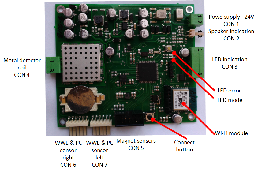
The purpose of the connectors is as follows
- CON 1 - power connection 12..24 VDC / VAC
- CON 2 - connection of an electromagnetic loudspeaker (speaker) 4 - 8 Ohm, or a sound amplifier
- CON 3 - connection of LED indication and / or buzzer. The pin assignments are shown in Table. 1
- CON 5 - connection of a loop from magnets sensors
- CON 6, 7 - connection of distance sensors for detection of prohibited passes and visitor counting (WWE - wrong way exit, PC - pass counter)
- LED mode - LED for indicating the operating modes of the system
- LED error - LED for indicating errors and system faults
- Connect button - the button for entering the mode of setting up a connection to the Wi-Fi network
Table 1. Pin assignment of the connector of the display CON 3
| Pin 1 | +12 V |
| Pin 2 | Magnet with trolley (RED) |
| Pin 3 | Magnet (GREEN) |
| Pin 4 | Metal (BLUE) |
| Pin 5 | WWE Left |
| Pin 6 | WWE Right |
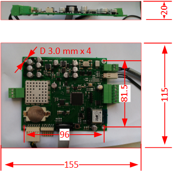
The overall dimensions
Figure 2 shows the overall dimensions of the board with attached connectors presented. And also the size and center-to-center distance of mounting holes on the board.

