Bidirectional pass counter v.1.x
Contents
Description
The counter consists of two modules:
- emitter - with one LED in the middle of the front panel (Fig. 1).
- receiver - module with LED in the middle of the front panel and two holes on the edges of the front panel (Fig. 2). Also on this module top you can find a narrow hole to access the button to activate the WiFi setting mode (Fig. 3).
Both units have a rectangular hole for the power cord at bottom side (Fig. 4).
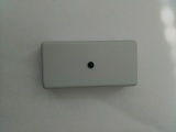
Fig. 1. Emitter
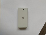
Fig. 2. Receiver
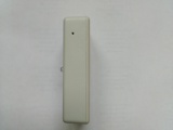
Fig. 3. Receiver. Top view
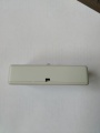
Fig. 4. Bottom view


Specifications
| Maximum distance between emitter and receiver | 6 meters |
| IR wavelength | 940 nm |
| Modulation frequency of the IR signal | 38 kHz |
| Power supply | 5 — 24 V DC |
| Communication standard | 802.11b/g/n (WiFi) network with a password only |
| Used communication protocols | TCP / IP, TLS 1.2, HTTPS, WebSocket |
| Power Consumption | |
| emitter | no more than 100 mW |
| receiver | 1 W |
| Operating temperature range | 0°C — 40°C, with relative humidity of 80% |
| Dimensions (WxHxD) | 80mm x 40mm x 20mm |
| Material hull | ABS plastic |
| Color | grey, black |
Installation
- Connect the power cords to the modules. If you connect the emitter power is necessary to observe the polarity ( "+" - near the wall, Fig. 5).
- Fix the modules on both sides of the aisle at a height of 1.20 — 1.40 meters. The receiver must be placed horizontally (to account for the direction of the input/output).
- Connect the power supply.
- The efficiency of the emitter can be checked using the smartphone camera. When viewed from the front side on the emitter LED from a short distance through the smartphone's camera, LED of running emitter will be painted in red-blue/purple color (Fig. 6).
- Receiver LED will flashing red and/or green in the different modes:
- Normal: the green every 5 seconds and/or at the intersection of the beam visitor;
- Setup mode: the green 10 Hz;
- Overlap beam: frequent blinking red (~ 10 Hz). The mode is set when there is no signal from the transmitter for 25 seconds;
- There is no WiFi network: the red every 5 seconds.
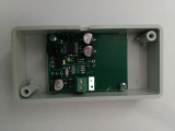
Fig. 5. Emitter. The polarity of the connection
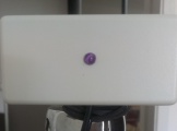
Fig. 6. LED of working emitter


WiFi Setup
All Baozam devices use the same WiFi Setup procedure. The difference is in where the setup button is placed and how it looks. The counter WiFi setup button is inside the narrow hole at the top of the receiver (Fig. 3). Button should be pressed with a toothpick. Sometimes you should put a toothpick at a small angle. When you press the button you feel (not hear) a click.
Setting and checking the operation of the device
All Baozam devices have common interface for tuning via the Internet. Please, read details at Device tuning via the baozam.net website page.
You should check:
If the emitter beam hits the receiver sensors (parameters left sensor & right sensor).
- Switch on sensor monitors (left sensor, right sensor). Normal values range 5 - 6.
- If the reading is less than 5, the emitter and receiver are not aligned or something breaks the beam. Adjust the alignment, clean the beam path.
- If values are greater than 7 look for the source of noise.
The direction of the entrance/exit.
- By default, the input direction is from left to right relatively to the receiver.
- Switch on monitoring parameter count_in & count_out. Break the beam ...
- Change the direction by using the Mode Control button. Use the drop-down button LEFT to RIGHT is ENTER or LEFT to RIGHT is EXIT to select the desired direction.
Important!
If you have changed any parameter, be sure to save the changes (Settings --> Save). Otherwise, when you switch the device off your settings will be lost.