Difference between revisions of "Bidirectional pass counter v.1.x"
m (Baya moved page Pass pounter in two directions to Bidirectional pass pounter) |
m (Baya moved page Bidirectional pass pounter to Bidirectional pass counter) |
(No difference)
| |
Revision as of 15:13, 8 September 2016
Contents
Description
The counter consists of two modules:
- emitter - with one LED in the middle of the front panel (Fig. 1).
- receiver - module with LED in the middle of the front panel and two holes on the edges of the front panel (Fig. 2). Also on this module top you can find a narrow hole to access the button to activate the WiFi setting mode (Fig. 3).
Both units have a rectangular hole for the power cord at bottom side (Fig. 4).
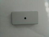
Fig. 1. Emitter
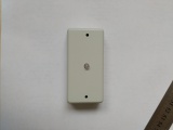
Fig. 2. Receiver
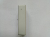
Fig. 3. Receiver. Top view
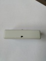
Fig. 4. Bottom view


Specifications
| Maximum distance between emitter and receiver | 6 meters |
| IR wavelength | 940 nm |
| Modulation frequency of the IR signal | 38 kHz |
| Power supply | 5 — 24 V DC |
| Communication standard | 802.11b/g/n (WiFi) network with a password only |
| Used communication protocols | TCP / IP, TLS 1.2, HTTPS, WebSocket |
| Power Consumption | |
| emitter | no more than 100 mW |
| receiver | 1 W |
| Operating temperature range | 0°C — 40°C, with relative humidity of 80% |
| Dimensions (WxHxD) | 80mm x 40mm x 20mm |
| Material hull | ABS plastic |
| Color | grey, black |
Installation
- Connect the power cords to the modules. If you connect the emitter power is necessary to observe the polarity ( "+" - near the wall, Fig. 5).
- Fix the modules on both sides of the aisle at a height of 1.20 — 1.40 meters. The receiver must be placed horizontally (to account for the direction of the input/output).
- Connect the power supply.
- The efficiency of the emitter can be checked using the smartphone camera. When viewed from the front side on the emitter LED from a short distance through the smartphone's camera, LED of running emitter will be painted in red-blue/purple color (Fig. 6).
- Receiver LED will flashing red and/or green in the different modes:
- Normal: the green every 5 seconds and/or at the intersection of the beam visitor;
- Setup mode: the green 10 Hz;
- Overlap beam: frequent blinking red (~ 10 Hz). The mode is set when there is no signal from the transmitter for 25 seconds;
- There is no WiFi network: the red every 5 seconds.
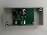
Fig. 5. Emitter. The polarity of the connection
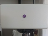
Fig. 6. LED of working emitter


WiFi Setup
At the receiver, the top has a narrow hole to access the button to activate the WiFi setting mode (Fig. 3). Button is pressed with a toothpick. Sometimes an angle. When pressed felt (not heard) a click. After clicking on the button the device goes into setup mode to five (5) minutes. After this time the device automatically returns to normal operation. In setting mode the device creates the WiFi access point (network name: baozam, password: mazoab123).
- In some cases, the process of creating a WiFi access point may take up to 20 seconds.
Connect your smartphone/laptop to the WiFi «baozam» AP. At the same time, you can connect only one smartphone/laptop to the device AP.
- In this case, the laptop/smartphone can display a message about unavailability of the Internet - this should be ignored (to setup WiFi we need access to the device, not to the Internet).
- On some smartphones the mobile internet must be switched off (temporarily) to guarantee you receive the network settings from the device.
- Some smartphones don't issue about incorrect password, and just trying to connect to the device AP again and again.
In your browser type the page address http://192.168.111.1/ of the device WiFi settings page. Follow the prompts on the page (Fig. 7).
Setting is divided into four stages (Fig. 7).
- Connecting to the device WiFi access point. In some cases, during the WiFi networks scanning and/or at the connection to the selected WiFi network, the device is forced to change the physical channel WiFi. Communication with the device may disappear and then you will need to re-connect your smartphone to the device WiFi access point.
- Connecting to the device. Information stage.
- Connecting to a WiFi network that the device will use to transmit data to the cloud. Stage has a separate screen (Fig. 8). At this point you can enter the name of your WiFi network in «WiFi SSID» field. In the «WiFi Key» - the network password. The device does not work through the open (no password) network. You can request the device to scan for available WiFi networks and show you a list («Scan WiFi Networks» button, Fig. 8), from which you can select the desired AP. When you select a network from the list the network password dialog pops up. Click «Connect» button after selecting a network and entering AP password. The device attempts to connect to the selected WiFi network.
- Connecting to the cloud. In case of a successful connection to the WiFi AP the device will save the setting and display a message with the received url from the cloud (Fig. 9), otherwise an error message. Also, after the issuance of the page device will close its access point («baozam»), which will lead to reconnection of your smartphone/laptop to your WiFi network (depending on your smartphone/laptop it can take different times, tens of seconds).
- In some cases, when special rules of work on your network, the device can not connect to the cloud. Check your network settings.
- Important. The device does not passes the WiFi key in the cloud.
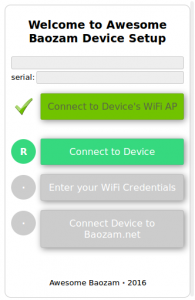
Fig. 7. WiFi setup screen
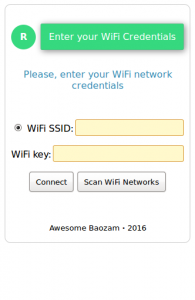
Fig. 8. WiFi SSID and key entry screen
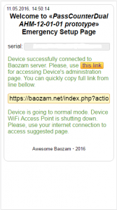
Fig. 9. The screen with the device url received from the cloud


Setting and checking the operation of the device
- Go to the page at https://baozam.net
- In the "Inventory" section, select the desired device.
- Over the device page, click on the link «Tuner». When the next transfer data to the cloud the device will go into the settings mode.
- The device sends data to the cloud every five (5 minutes). The device immediately reports about cutting/opening the beam, turning on. To avoid to wait up to five minutes, you can: a) cut off the beam - a message in 25 seconds, b) turn off/on the device.
- After the device come into the setup mode you will get a message at the «Tuner» page, and all device parameters will be displayed.
- Hovering the cursor over the "blue" parameter causes the appearing of «Stream & Monitor» buttons.
- Stream - on/off sending this parameter to the cloud.
- Monitor - on/off immediate displaying parameter in the "Monitor" box at the page.
- You should check
- Entering the emitter beam on the receiver sensors (parameters «left sensor» & «right sensor»). Turn on sensor monitors. Normal values range 5 - 6. If the reading is less than 5, the emitter and receiver are not aligned or something overlaps the beam. Adjust the alignment, clean the beam path. If values are greater than 7 look for the source of noise.
- The direction of the entrance/exit. By default, the input direction is from left to right relative to the receiver. Turn on monitoring parameter «count_in_tmp». Cross the beam ... change the direction by using the «Mode Control» button. Use the drop-down button «LEFT to RIGHT is ENTER» or «LEFT to RIGHT is EXIT» to select the desired direction.
- Important! If you change the direction of the passage, be sure to save your changes («Settings» button - «Save»). Otherwise, when you turn off the device power your settings will be lost.